
PSA System
The PSA Nitrogen Generator works with adsorption media in side the vessel is called CMS ( Carbon Molecular Sieve), In N2 generator the Oxygen in the Air is adsorbed by CMS and the N2 passes out of the vessel at the desired purity up to 99.999 (10ppm Oxygen) . A programmable controller operates the process valves on alternating cycle, with built-in logic for automatic stop/start. Nitrogen flow and purity remain constant regardless of peak demands.
Contact us
Key Features
Plug & Play Nitrogen generator, Compact, mobile and silent 10 to 20l / min flow at 3.8 bar to 6.5 bar Integrated PSA columns Integrated oxygen analyzer Fully automatic, fully digitalize can be monitor by every screen.
High purity Systems
PSA Nitrogen generators are typically used in applications where the purity requirement is higher than 99.5% (0.5% O2 or below). PSA can go up to 99.999(based on Oxygen ppm) . as per requirements
Lowest Maintenance
Maintenance is easy as well. You will only be required to change the filters, operating valves every year PSA Nitrogen Generator is too simple – just start up the PSA Nitrogen generators by a switch.
PSA System
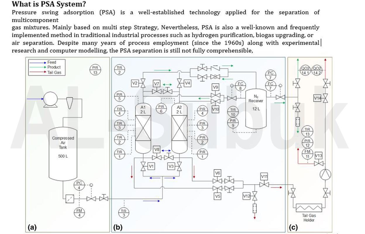
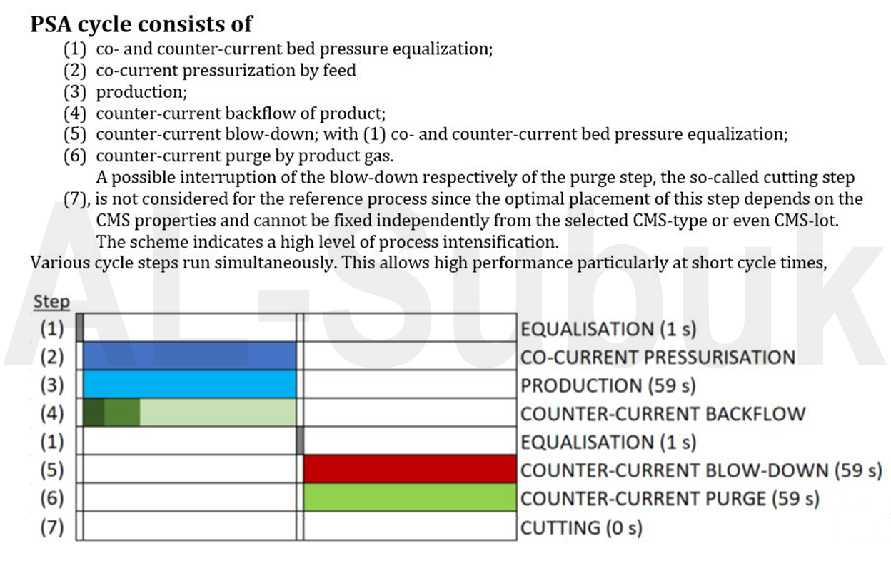
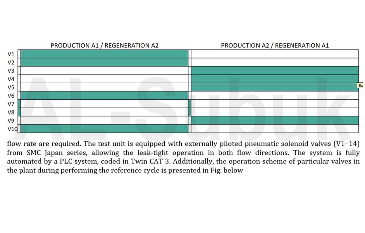
The global demand for highly purified gases provided by energy-efficient separation processes grows steadily for decades. An example of particular industrial relevance is nitrogen generated by pressure swing adsorption (PSA System) from compressed air. A kinetically based separation of oxygen from nitrogen is possible by means of carbon molecular sieves (CMS) since oxygen adsorbs remarkably faster in CMS than nitrogen. Even high product purities (5–1000 ppm O2) are easily achievable in commercial generators. However, only a few studies present experimental findings in this purity range. That comes as no surprise since experimental conditions are not standardized and the determination of N2- PSA performance indicators still creates an experimental challenge.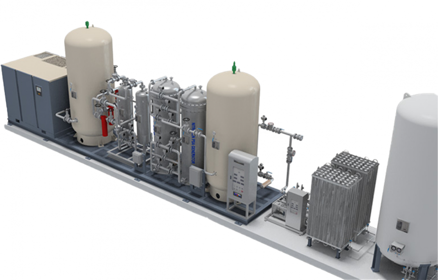
Operationalization of performance indicators in PSA plants
PSA plants are operated in two different modes—either with a constant feed flow rate or with a constant product flow rate. The first option is preferred in lab-scale plants, whereas the second option is typically implemented in pilot and commercial plants. This has consequences for the determination of the performance indicators, at certain purity, obtained by explicit methods and by implicit methods (GMB) when assuming a constant density of the feed and product gas. Any integration of a flow causes errors due to the limitation in scan speed of the flow meters, which will be discussed later in detail. At this point, a simple alternative shall be introduced, which consists of the collection of the fluctuating product or tail gas stream during one or more cycles in evacuated gas holders. This makes it possible to determine flow rates independent from the running process with conventional, but very precise methods under comparable constant flow conditions. In this investigation, a PSA operation with a constant
product flow rate was adjusted and thus, the tail gas flow was selected as that stream which was collected separately
in a gas holder and then analyzed under constant flow conditions. it can be concluded that in
case of a constant product flow rate the productivity should be determined just by direct reading, whereas for the air demand the GMB and the OMB should be applied since the tail gas and the product flow rates are both constant in these equations. However, if for instance the feed gas flow meter would be placed between compressor and tank, the air flow measurement will not vary significantly during the cycle and an integrated flow rate can be precise enough. But the final intention of the presented experimental set-up is the verification of a mathematical PSA model, which requires a position of the feed gas flow meter as close to the adsorbers as possible. In case of a PSA operation with a constant feed flow rate it comes to different conclusions. Assuming a collection of the product flow in a gas holder it is just possible to apply explicit methods. Only if the tail gas is additionally collected in a gas holder the utilization of the implicit methods for calculating precise PIs is possible. If the collection of gas streams in gas holders is not feasible, accuracy limitations of integrated flow parameters have to be accepted.
Verification strategy
A perfectly determined performance indicator ( Oxygen Analyzer ) attains exactly the same value whether calculated from the two material balances (implicit) or directly read from the flow meters (explicit). In fact, it is necessary to accept a certain tolerance of incompatibilities between values due to inevitable measuring errors. Any exceeding significant difference in values of performance indicators are the evidence of a faulty operation of the PSA system, e.g. leakages, incorrect calibration of measuring devices, errors in transmitting electrical signals to the equipment, errors in the software code, accumulation of pollutants in valves, diffusion intake due to porous or inadequate piping or seals, or exhausted filters.
A performance indicator value is considered to be determined correctly when the difference between the results obtained from the different direct readings) does not exceed a tolerance level of 1% determined as a relative error δexp. If δexp between differently calculated performance indicators is lower than 1%, obtained values are considered as correct. If δexp is larger than 1%, obtained values are discarded. Admittedly, this 1%-tolerance level of δexp seems to be set arbitrarily, however, justified by laboratory experience gained in decades of quality control. Additionally, separate performance indicators of each single adsorber column can also be calculated. This allows the disclosure of potential imbalances between the adsorber columns, which sometimes leads to an accelerated detection of operation faults.
How to Verify the Oxygen Analyzer results,
In order to investigate the efficiency of high-purity N2- PSA plants under standardized conditions, practically performance of four operation are performed.
So we use high Purity Oxygen Analyzers which are verified by high purity certified Calibration gasses of certain ppm of Oxygen Balance with Nitrogen from a Highly Certified Gas Providing company.
We can use the following Certified Calibration Gasses to perform testing of Oxygen Analyzer on Site,
- 1). Calibration GAS Cylinder. 10ppm Oxygen / Balance Nitrogen, Cylinder Pressure 100 Bar With regulator to 4 Bar OutPut.
- 2). Calibration GAS Cylinder. 901ppm Oxygen / Balance Nitrogen, Cylinder Pressure 100 Bar With regulator to 4 Bar OutPut.
- 3). Calibration GAS Cylinder. 4990ppm Oxygen / Balance Nitrogen, Cylinder Pressure 100 Bar With regulator to 4 Bar OutPut.
- 4). Calibration GAS Cylinder. 9024ppm Oxygen / Balance Nitrogen, Cylinder Pressure 100 Bar With regulator to 4 Bar OutPut.
Above all Calibration glasses or any available Oxygen Gas with ppm-level balance with Nitrogen from a certified Source,
Application
Injection molding, Purge, Laser cutting, Fire extinguisher, Packing, Beer, Heat treatment, Soldering, Reflow, Photo Lab and Electronics
• Air Compressor: Air compressor is the equipment to produce compressed air. Compressed air is used for separating nitrogen from the air. In the process of compression, moisture and heat happen. To remove them, a built-in or independent air dryer and after-cooler are necessary.
• Air receiver Tank: Air receiver tank is the equipment to keep supplying the compressed air of certain pressure to the nitrogen generator stably. It is also for the purpose of handling a load of compressor properly.
• Filter: Filter is used for removing dust, particle, and oil, etc. in compressed air.
• Desiccant air dryer: This is used for removing moisture by using an adsorbent. It consists of two adsorbers and has the repeated cycles of adsorption and regeneration.
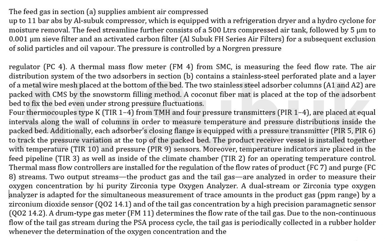
• PSA Generator: In order to separate nitrogen from compressed air, CMS(Carbon Molecular Sieve) is used as an adsorbent. PSA system consists of pressurization, production, purge, equilibrium of pressure, and regeneration.
• Nitrogen storage Tank: It is a buffer (storage) tank to supply the oxygen at a certain pressure, flow, purity.
• LCP: LCP has control of the whole system into operation automatically or manually. It also indicates the purity, pressure, and flow of the produced nitrogen.
• Nitrogen supply: The purity of the produced nitrogen is up to 99.999%. Flow and pressure depend on the customer`s needs.
• LN2 Storage tank: It is the equipment for storing liquid nitrogen.
• LN2 Vaporizer: It is the equipment for changing nitrogen from a liquid into gas through vaporization. Gas supply unit: In order to supply vaporized nitrogen with the certain pressure
• Gas supply unit: In order to supply vaporized nitrogen with the certain pressure
• LCP: It controls the heater that is used when the vaporized nitrogen of a certain temperature is required.
N2 PSA SYSTEM TYPE
| MODEL | N2 FLOW(NM3/H) | Size(W*D*H) | WEIGHT(kg) |
|---|---|---|---|
| N- 5 | 5 | 545*520*1461 | 287 |
| N- 7 | 7 | 685*570*1388 | 356 |
| N- 10 | 10 | 685*570*1743 | 432 |
| N- 15 | 15 | 800*640*1811 | 563 |
| N- 20 | 20 | 850*680*1906 | 647 |
| N- 25 | 25 | 850*680*2238 | 802 |
| N- 30 | 30 | 940*830*2152 | 925 |
| N- 40 | 40 | 1080*812*2229 | 1120 |
| N- 50 | 50 | 1080*812*2619 | 1318 |
| N- 70 | 70 | 1324*1108*2976 | 1588 |
| N- 100 | 100 | 1418*1160*3422 | 2096 |
| N- 120 | 120 | 1519*1210*3340 | 2396 |
| N- 150 | 150 | 1722*1311*3331 | 3109 |
| N- 180 | 180 | 1824*1363*3642 | 3572 |
| N- 200 | 200 | 2126*1513*3387 | 3955 |
| N- 250 | 250 | 2126*1513*3387 | 4753 |
| N- 300 | 300 | 2532*1717*3444 | 5506 |
| N- 350 | 350 | 2735*1818*3474 | 6273 |
| N- 400 | 400 | 2938*2019*3485 | 7008 |
| N- 500 | 500 | 3239*2145*3564 | 8440 |
Standard calibration balance with nitrogen Gas
| Standard Gas | Reference Gas | Measured Out Put | Calculated ppm | Decision |
|---|---|---|---|---|
| 9024 ppm | 18.438 mA | 18.448 mA | 9030 ppm | GOOD |
| 4990 ppm | 11.984 mA | 11.998 mA | 4999 ppm | GOOD |
| 901 ppm | 5.442 mA | 5.453 mA | 908 ppm | GOOD |
| 91 ppm | 4.146 mA | 5.155 mA | 97 ppm | GOOD |
| 19.6 ppm | 4.031 mA | 4.043 mA | 27 ppm | GOOD |
Need a help?
Please Fill The Form Our Team Will Contact You As Soon As Possible.